


Gate monitoring system solution
Time:2015-06-18 04:35
Read:13527
Source:Internet
summary
With the rapid development of communication technology and control technology, computer monitoring system is widely used in hydropower stations, especially when the control mode of "nobody on duty and few people on duty" is put forward, hydropower stations, water conservancy projects and other projects put forward new requirements for the automation level of gate monitoring and management.
According to the market demand, the new generation gate control system developed by our company takes the programmable controller as the control core, adopts the industrial Ethernet technology, and configures a high-performance upper computer, which makes the system structure simple and clear, greatly improves the reliability and availability of the system, reduces the intensity of commissioning, operation and maintenance, and becomes an indispensable equipment for the hydropower station with "no one on duty and few people on duty".
The system has simple structure and convenient operation. The operator only needs to input the height of the gate to be adjusted in the upper computer control screen and confirm, and the gate monitoring system can automatically complete the start and stop of the gate as required. High control accuracy and fast response speed.
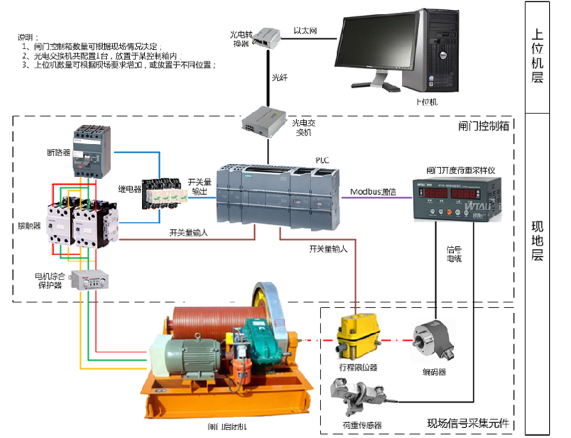
System structure
The control system adopts a hierarchical and distributed structure. The whole system is divided into two layers. The upper layer is the monitoring unit of the central control room and the lower layer is the local operation unit. Monitor and control all gates; PLC is used as the main control element to realize the control of the local layer. Control boxes shall be provided according to the number of gates. Each gate shall be provided with one control box, which shall be placed beside the controlled gate hoist. The remote monitoring of the gate can be realized on the upper computer, and the gate can also be operated locally through the button on the control box.
The rotary encoder is used to collect the gate height in real time, and the SSI (gray code) coded signal is sent to the opening load measuring and controlling instrument. The opening load measuring and controlling instrument will display the data on its own panel after the data is converted, and transmit the data to the PLC through MODBUS communication for the operator to view. At the same time, it also sends signals to the central control room to realize remote monitoring.
The control system uses 100m Industrial Ethernet to directly communicate between the upper computer and each control cabinet. So as to realize the monitoring and control of each gate by the monitoring computer in the central control room, and even if one of the equipment fails, the operation of other equipment will not be affected. It is truly a hierarchical and distributed control mode.
The system structure diagram is as follows:

For remote users who cannot connect to optical fiber, we use GPRS transmission solution.

System characteristics
High accuracy: the system uses multi turn absolute encoder, and the gate operation accuracy can reach mm;
High reliability: the system is equipped with electrical and mechanical limit protection, electrical operation protection, etc.
Industrial communication network: Industrial Ethernet communication is adopted between the upper computer and the local equipment, and there will never be data change caused by communication interference;
High speed: the combination of high-performance PLC, upper computer and industrial Ethernet makes the communication delay less than 1ms, and the change of field signal will be transmitted to the display screen of upper computer at the fastest speed;
Simple structure: PLC → communication network → upper computer, effectively reducing investment cost and maintenance cost;
Each unit is relatively independent: the upper computer and each gate control cabinet are relatively independent. Failure of any control cabinet will not affect the operation of other gates;
Diversity of operation modes: it can complete local manual control, remote manual control, remote precise control, system automatic control and other operations;
system function
1) Monitoring function
The upper computer can complete the functions of screen display, report printing, parameter setting and operation control, and comprehensively monitor the operating conditions of the main equipment of the whole gate system.
2) Remote dispatching function
It can receive commands from remote dispatching and automatically control and adjust the gate.
3) Event sequence recording function
The accident and fault signals of the main equipment of the whole gate system and the fault signals of the monitoring system shall be recorded in sequence. According to the time sequence of the fault signal, record the name and displacement time of the fault signal, including year, month, day, hour, minute and second.
4) Operation record function
Record the name, time and success of the operator's operation on the human-machine interface.
5) Fault alarm function
When the monitoring object fails, the system can automatically alarm; In case of an accident, the system can automatically stop the operation of the gate and give an alarm. All fault signals are warned by the fault indicator in the gate control box. The upper computer can display detailed fault information, such as whether the local equipment has fault, whether the gate is stuck, and whether the gate operates abnormally.
6) System self diagnosis function
When the monitoring system is running online, the hardware and software in the system will be self diagnosed. PLC has self diagnosis function, which can detect the error of outgoing line during the program, and correct and recover it by itself. At the same time, PLC can also detect the action of gate load meter and thermal overload relay, the coding signal sent by rotary encoder, encoder error or communication disconnection. PLC will send fault signal immediately;
7) Real time control function
Precise control: the height of the gate required to be operated can be set in the upper computer operation screen. After the execution is determined, the control system will automatically complete the gate control to make the gate run to the specified height;
Manual control: the upper computer is also equipped with manual operation buttons, including "up, down, stop and emergency stop", which can be operated manually according to the operation requirements. The manual control is protected by the upper and lower limits, and automatically stops when the operation reaches the limit position;
Automatic control: this function is optional. The system can automatically complete the opening and closing of the gate according to the water level difference between the upstream and downstream. This function needs to collect the water level of the upstream and downstream separately;
The detailed operation status of the gate is transmitted to the central control room in the form of communication. And the hard node of the original gate control system is retained to transmit the gate full open / close status, power on / off status, and gate remote / local operation status.
The control box is equipped with remote / local switching function. Under normal conditions, the operation handle is placed at the remote position and operated by the upper computer. The manual control of the gate is realized by the local control. In this mode, the local control device can perform various sampling display and monitoring alarm, and realize the automatic closed-loop control of the gate. The gate can be started and stopped at any position within the gate travel range according to the requirements of the operator. This function can be realized in the central control room and local operation. The upper limit, upper limit and lower limit positions of the gate can be set, and can be displayed and queried separately;
8) Protection function
The control box is equipped with phase break protection, upper limit protection, lower limit protection and load protection. When the gate is opened to the upper limit, the gate cannot continue to rise.
Mechanical interlocking reversible contactor and circuit breaker with shunt tripping function are used to control the gate motor. Each gate control can realize remote emergency stop, prevent the power supply circuit from being cut off after the motor is stuck, and protect the motor and prevent misoperation.
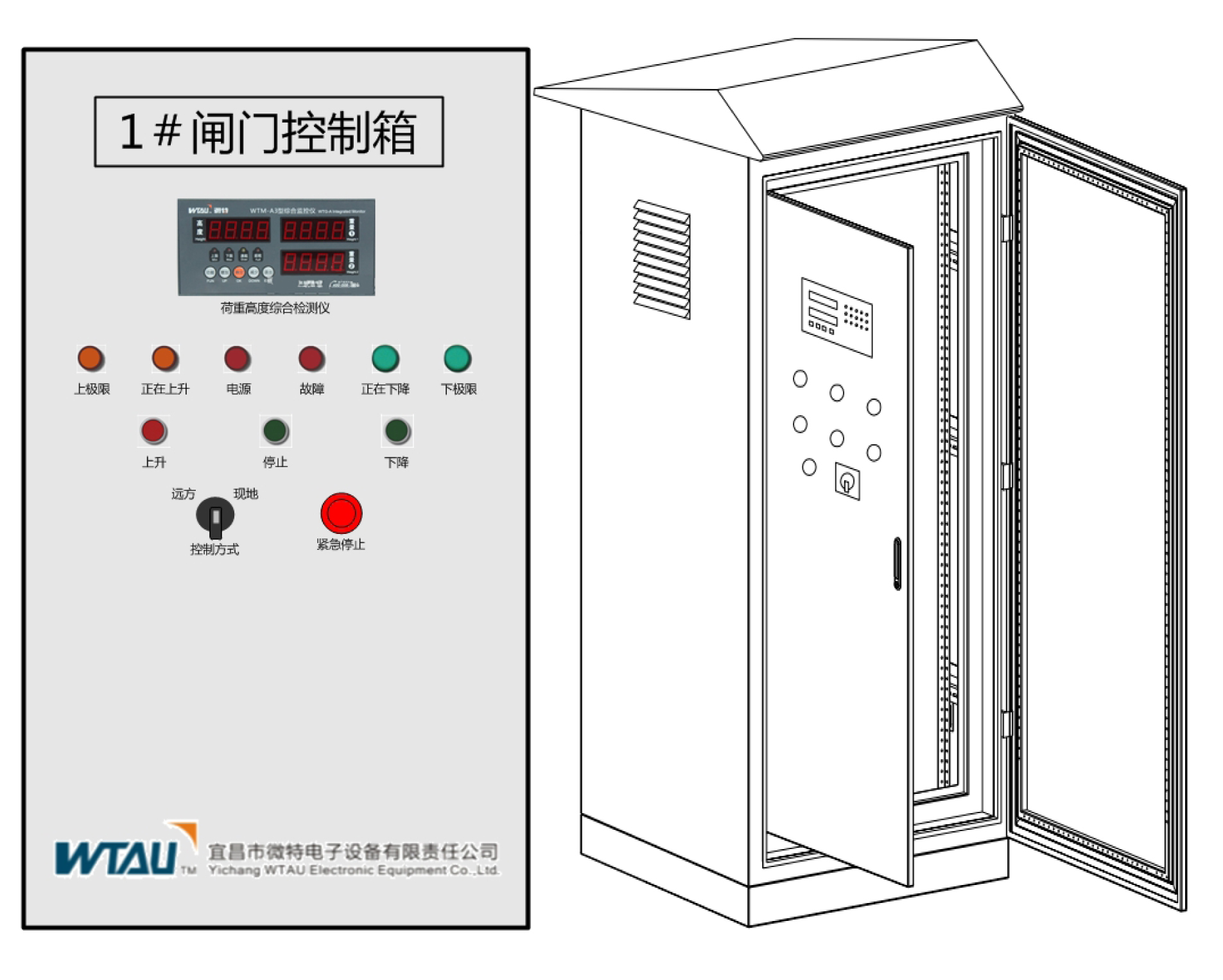
Control cabinet
The following figure shows the control cabinet for indoor hoist designed by our company. The cabinet size is determined according to the hoist motor capacity. In case of outdoor hoist, the control box shall be replaced with stainless steel outdoor type. As shown below:
With the rapid development of communication technology and control technology, computer monitoring system is widely used in hydropower stations, especially when the control mode of "nobody on duty and few people on duty" is put forward, hydropower stations, water conservancy projects and other projects put forward new requirements for the automation level of gate monitoring and management.
According to the market demand, the new generation gate control system developed by our company takes the programmable controller as the control core, adopts the industrial Ethernet technology, and configures a high-performance upper computer, which makes the system structure simple and clear, greatly improves the reliability and availability of the system, reduces the intensity of commissioning, operation and maintenance, and becomes an indispensable equipment for the hydropower station with "no one on duty and few people on duty".
The system has simple structure and convenient operation. The operator only needs to input the height of the gate to be adjusted in the upper computer control screen and confirm, and the gate monitoring system can automatically complete the start and stop of the gate as required. High control accuracy and fast response speed.
System structure
The control system adopts a hierarchical and distributed structure. The whole system is divided into two layers. The upper layer is the monitoring unit of the central control room and the lower layer is the local operation unit. Monitor and control all gates; PLC is used as the main control element to realize the control of the local layer. Control boxes shall be provided according to the number of gates. Each gate shall be provided with one control box, which shall be placed beside the controlled gate hoist. The remote monitoring of the gate can be realized on the upper computer, and the gate can also be operated locally through the button on the control box.
The rotary encoder is used to collect the gate height in real time, and the SSI (gray code) coded signal is sent to the opening load measuring and controlling instrument. The opening load measuring and controlling instrument will display the data on its own panel after the data is converted, and transmit the data to the PLC through MODBUS communication for the operator to view. At the same time, it also sends signals to the central control room to realize remote monitoring.
The control system uses 100m Industrial Ethernet to directly communicate between the upper computer and each control cabinet. So as to realize the monitoring and control of each gate by the monitoring computer in the central control room, and even if one of the equipment fails, the operation of other equipment will not be affected. It is truly a hierarchical and distributed control mode.
The system structure diagram is as follows:
For remote users who cannot connect to optical fiber, we use GPRS transmission solution.
System characteristics
High accuracy: the system uses multi turn absolute encoder, and the gate operation accuracy can reach mm;
High reliability: the system is equipped with electrical and mechanical limit protection, electrical operation protection, etc.
Industrial communication network: Industrial Ethernet communication is adopted between the upper computer and the local equipment, and there will never be data change caused by communication interference;
High speed: the combination of high-performance PLC, upper computer and industrial Ethernet makes the communication delay less than 1ms, and the change of field signal will be transmitted to the display screen of upper computer at the fastest speed;
Simple structure: PLC → communication network → upper computer, effectively reducing investment cost and maintenance cost;
Each unit is relatively independent: the upper computer and each gate control cabinet are relatively independent. Failure of any control cabinet will not affect the operation of other gates;
Diversity of operation modes: it can complete local manual control, remote manual control, remote precise control, system automatic control and other operations;
system function
1) Monitoring function
The upper computer can complete the functions of screen display, report printing, parameter setting and operation control, and comprehensively monitor the operating conditions of the main equipment of the whole gate system.
2) Remote dispatching function
It can receive commands from remote dispatching and automatically control and adjust the gate.
3) Event sequence recording function
The accident and fault signals of the main equipment of the whole gate system and the fault signals of the monitoring system shall be recorded in sequence. According to the time sequence of the fault signal, record the name and displacement time of the fault signal, including year, month, day, hour, minute and second.
4) Operation record function
Record the name, time and success of the operator's operation on the human-machine interface.
5) Fault alarm function
When the monitoring object fails, the system can automatically alarm; In case of an accident, the system can automatically stop the operation of the gate and give an alarm. All fault signals are warned by the fault indicator in the gate control box. The upper computer can display detailed fault information, such as whether the local equipment has fault, whether the gate is stuck, and whether the gate operates abnormally.
6) System self diagnosis function
When the monitoring system is running online, the hardware and software in the system will be self diagnosed. PLC has self diagnosis function, which can detect the error of outgoing line during the program, and correct and recover it by itself. At the same time, PLC can also detect the action of gate load meter and thermal overload relay, the coding signal sent by rotary encoder, encoder error or communication disconnection. PLC will send fault signal immediately;
7) Real time control function
Precise control: the height of the gate required to be operated can be set in the upper computer operation screen. After the execution is determined, the control system will automatically complete the gate control to make the gate run to the specified height;
Manual control: the upper computer is also equipped with manual operation buttons, including "up, down, stop and emergency stop", which can be operated manually according to the operation requirements. The manual control is protected by the upper and lower limits, and automatically stops when the operation reaches the limit position;
Automatic control: this function is optional. The system can automatically complete the opening and closing of the gate according to the water level difference between the upstream and downstream. This function needs to collect the water level of the upstream and downstream separately;
The detailed operation status of the gate is transmitted to the central control room in the form of communication. And the hard node of the original gate control system is retained to transmit the gate full open / close status, power on / off status, and gate remote / local operation status.
The control box is equipped with remote / local switching function. Under normal conditions, the operation handle is placed at the remote position and operated by the upper computer. The manual control of the gate is realized by the local control. In this mode, the local control device can perform various sampling display and monitoring alarm, and realize the automatic closed-loop control of the gate. The gate can be started and stopped at any position within the gate travel range according to the requirements of the operator. This function can be realized in the central control room and local operation. The upper limit, upper limit and lower limit positions of the gate can be set, and can be displayed and queried separately;
8) Protection function
The control box is equipped with phase break protection, upper limit protection, lower limit protection and load protection. When the gate is opened to the upper limit, the gate cannot continue to rise.
Mechanical interlocking reversible contactor and circuit breaker with shunt tripping function are used to control the gate motor. Each gate control can realize remote emergency stop, prevent the power supply circuit from being cut off after the motor is stuck, and protect the motor and prevent misoperation.
Control cabinet
The following figure shows the control cabinet for indoor hoist designed by our company. The cabinet size is determined according to the hoist motor capacity. In case of outdoor hoist, the control box shall be replaced with stainless steel outdoor type. As shown below:
Previous:Water level measurement and control system of hydropower station and reservoir
Next article:WTDC type hydraulic grab beam deep water monitoring system
Free hotline
400-008-2600
No.6 Gangcheng Road,Yichang,Free Trade Zone(Hubei) China

Wechat Mp